Laser Radiation

When handling optical fibers, do not stand close to or look into the optical fiber outlet directly without eye protection.

Use of controlsor adjustment or performance of procedures other than those specified herein may result in hazardous radiation exposure.
-
A laser transceiver is used in optical transmission system and related test tools. The laser transmitted through unterminated optical fibers or connectors has very high power density and is invisible to human eyes. A beam of light can cause damage to the retina.
-
Looking into the end of an exposed optical fiber or broken optical fiber without eye protection from a distance of more than 150 mm (5.91 in.) will not cause eye injury. However, eyes may be damaged if an optical tool such as a microscope, magnifying glass, or eye loupe is used to view a bare optical fiber end.
-
Observe the following precautions to avoid laser radiation hazards:
-
Only trained personnel are authorized to operate the laser.
-
Wear protective goggles during laser or optical fiber operation.
-
Disconnect the light source before disconnecting optical fiber connectors.
-
Use optical fiber caps to protect the disconnected optical fiber connectors.
-
Use an optical power meter to measure optical power and verify that the light source is disconnected.
-
Do not look into an exposed optical fiber or connector terminal until the light source is off. Immediately install dust-proof caps onto exposed optical fiber connectors.
-
Ensure that the optical fibers and light source are disconnected before fiber cutting or splicing.
-
Ensure that there is no laser radiation before opening the front door of the optical transmission system.
-
Do not view optical fiber terminals or connectors with a microscope, magnifying glass, or eye loupe.
Installing Optical Modules and Connecting Optical Fibers
Context

· Do not look into bores of optical modules or connectors of optical fibers without eye protection.
· Thebend radius of an optical fiber must be at least 20 times larger than itsdiameter. Generally, the bend radius of optical fibers should be no less than40 mm.
· Installor remove optical fibers carefully to avoid damage to fiber connectors.
· If afiber connector is dirty, use an alcohol swab or a piece of air-laid paper togently wipe the fiber connector in one direction.
· Installdust plugs on idle optical ports.
Tools and Accessories
· ESD wrist strap or ESD gloves
· Scissors
· Insulation tape
· Corrugated pipe
· Fiber binding tape
· Engineering labels for optical fibers
· Tweezers (delivered with the switch)
Procedure
1�、Determine the number and type of ports to be connected and plan the cabling route.
2、Select optical fibers of appropriate modes,quantity, and lengths according to the optical module types, number of ports tobe connected, and measured cabling distance.
3��、Attach temporary labels on both ends of eachoptical fiber and write numbers on the labels. For details on how to numberoptical fibers, see Engineering Labels for Optical Fibers.
4、 Unroll optical fibers and bundle them. See Table 1 to determine the number of optical fibers in eachbundle. Cut protection pipes into appropriate lengths according to opticalfiber lengths, and then put optical fibers through the protection pipes. Wrapboth ends of a protection pipe with adhesive tape to prevent damage to opticalfibers.

When routing optical fibers in a corrugated pipe, you must wrap both ends of the pipe with adhesive tape to prevent shape edges of the pipe from damaging the optical fibers.
Table 1 lists the types and capacities of protection pipes.
Table 1 Protection pipe types andcapacities
|
Type
|
Maximum Number of Optical Fibers
|
|
Open corrugated pipe
|
60
|
|
Closed corrugated pipe
|
12
|
|
Winding pipe
|
l Pipe with an external diameter of 6 mm: 10
l Pipe with an external diameter of 20 mm: 20
|
5�����、 (Optional) Route optical fibers from the optical distribution frame to the cabinet along the planned path.
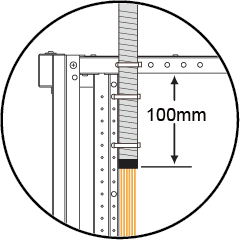
Open corrugated pipes are recommended. Keep100 mm of a protection pipe inside the cabinet, as shown in Figure 1.
Figure 1 Length of protection pipe inside the cabinet
6��、 Wear an ESD wrist strap or a pair of ESDgloves. When wearing an ESD wrist strap, insert the other end in the ESD jackof a device and ensure that the device is reliably grounded.
7����、 Remove dust plugs from the optical ports to beconnected and install optical modules on the optical ports.
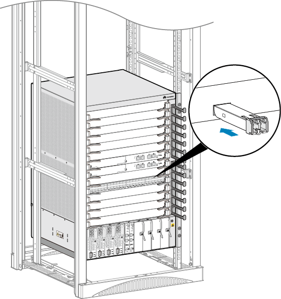
Hold the connector ofan optical module in the correct direction when inserting it into a port. Whenyou hear a click, the optical module is securely connected to the port. See Figure 3.
NOTE:
The topside of a QSFP+ optical module is the side with an L-shaped recess, as shown inFigure 2. When connecting a QSFP+ optical module to a port on a CSS card, makethe top side face down. When connecting a QSFP+ optical module to other typesof ports, make the top side face up. Do not insert the optical module backwards.
Figure 2 QSFP+ optical module
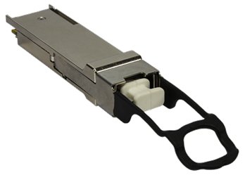
Figure 3 Installing an optical module
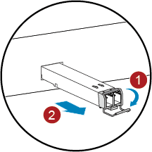
To remove an optical module, rotate the handle down, gently push the optical module, and then pullout the optical module by the handle. See Figure 4.
Figure 4 Removing an optical module
8、 Connect optical fibers to the optical modules.Remove dust plugs from the optical modules and insert fiber connectors into the corresponding optical ports. After verifying that all optical fibers are correctly connected, go to step 9.
To connect optical fibers to an optical module, align the fiber connector with the bores on theoptical module and insert the fiber connector. When you hear a click, the optical fiber is securely connected. See Figure 5.
Figure 5 Connecting optical fibers to an optical module
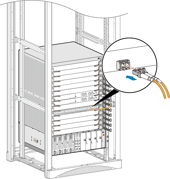
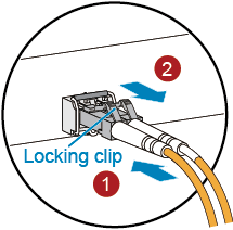
To remove an opticalfiber, gently push the fiber connector, and then pull the fiber connector whilepressing the locking clips. Do not forcibly pull the fiber connector. See Figure 6.
NOTE:
Ifmany optical fibers are connected to an interface card with a high portdensity, use the tweezers delivered with the switch to remove optical fibers.
Figure 6 Removing optical fibers
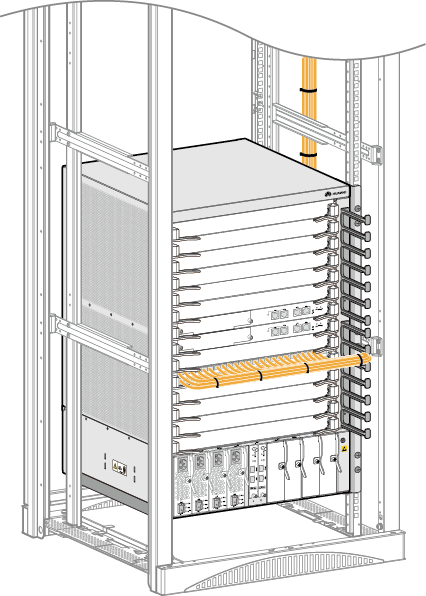
9����、Bundle optical fibers. Put optical fibers through the cable management frames of the corresponding slots and use fiber binding tapes to bundle optical fibers at 20 cm to 30 cm intervals. See Figure 7.
Figure 7 Bundling optical fibers
It is not recommended to connect copper cables and optical fibers to the same card because copper cables may block the routes of optical fibers. If the coppercables and optical fibers are used on the same card, connect the optical fibersto ports near the left side of the card and the copper cables to ports near theright side, as shown in Figure 8.
Figure 8 Connecting copper cables and optical fibers to the same card

10��、 Replace all the temporary labels on the optical fibers with permanent labels.
Follow-up Procedure
Use a rope to hang the tweezers in an appropriate place in the cabinet for later use.
Replacing an Optical Module
Context

When replacing an optical module, donot look into bores of the optical module without eye protection. The laseremitted from the bores may injure your eyes.

· Installor remove optical fibers carefully to avoid damage to fiber connectors.
· Optical modules are electrostatic-sensitive components; therefore, you must take ESDprotective measures when replacing optical modules.
· Donot insert an optical module backwards. If an optical module cannot be completely inserted into an optical port, do not force it into the port. Turn the optical module over and try again.
Observe the following rules to replacean optical module:
· Wear an ESD wrist strap or ESD gloves when replacing the optical module.
· Ensure that the new optical module has thesame center wave length and complies with the same standards as the old one.
· Before removing an optical module, unplug optical fibers from the optical module. Do not apply too much force when unplugging optical fibers. Otherwise, the optical module may be damaged.
· After removing optical fibers from optical modules, cover the ports of cards and bores of optical modules with dust plugs.
Tools andAccessories
· ESD wrist strap or ESD gloves
· Dust caps
· Dust plugs
· Alcohol swab
Procedure
1. Wear an ESD wrist strap or a pair of ESDgloves. When wearing an ESD wrist strap, insert the other end in the ESD jackof a device and ensure that the device is reliably grounded.
2. Record optical fiber locations on the oldoptical module and check whether the labels on the optical fibers are correctand legible. If any labels are illegible, make and attach new labels to thecables to ensure correct fiber connection on the new optical module.
3. Release the locking clip on the fiberconnector, gently push the fiber connector, and then pull out the optical fiber. After removing optical fibers from the optical module, cover fiber connectors with dust caps.
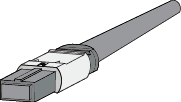
The locking clip varies on different fiber connectors. Figure1 shows the locking clips on an LC/PC connector.Hold down the locking clips when pulling the optical fibers. Figure 2 shows the locking clip on an MPO connector. The lockingclip is released automatically when you pull the MPO connector.
Figure 1 LC/PC connector
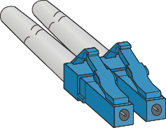
Figure 2 MPO connector
4. Release the latch of the optical module,gently push the optical module, and then pull it out. Cover the bores of theoptical module with dust plugs.
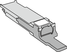
The latch varies on different optical modules. Figure 3 shows an optical module with a clasp latch. To releasethe clasp latch, rotate it down. Figure 4 shows an optical module with a tab latch. The tab latch is released when youpull it.
Figure 3 Optical module with a clasp latch
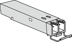
Figure 4 Optical module with a tab latch
5. Take out the new optical module from thepackage. Slowly insert the optical module into the optical port until you heara click.
NOTE:
Thenew optical module must have the same optical parameters as the remote optical module connected to it.
6. Find the optical fibers to be connected to the optical module according to labels on the optical fibers. Remove the dust capsfrom the fiber connectors and insert the optical fibers to bores of the optical module.
NOTE:
Ifthe optical module does not work, use an alcohol swab to wipe the fiber connectors in one direction, and then connect the optical fibers to the optical module again.
Guide to Using Optical Modules
Common Faults of an Optical Module
1. An optical module is not completely installedin position.
If the optical module is not completelyinstalled in position and the latch boss is not secured, the device cannot identify the optical module. After the optical module works for a long time, itwill be ejected under external stress.
2. The optical receptacle on an optical module iscontaminated.
If an optical module is not cleaned orprotected properly, contaminants may accumulate on the fiber pin in the opticalmodule. As a result, the coupling efficiency is reduced, optical signals arecut off, or even worse, the surface of the fiber pin is damaged permanently.
3. An optical module is burnt.
If high-power optical signals (caused by anoptical time domain reflectometer or self-loop test) are transmitted through anoptical module that is used for long-distance transmission but no opticalattenuator is used, the optical power will exceed the overload power of theavalanche photodiode (APD). Then the optical module is burnt.
The preceding faults lead to temporaryor long-term cut-off of optical signals; or even cause permanent damages to theoptical module, affecting communication services.
Measures to Prevent a Loosened OpticalModule
1. When installing an optical module, insert itin position. If you hear a click or feel a slight shake, it indicates that thelatch boss is secured.
If the latch boss is not secured, the goldfinger of the optical module is not in good contact with the connector on theboard. In this case, the link may be connected but optical signals will be cutoff or the optical module will be loosened when the optical module is shaken orhit.
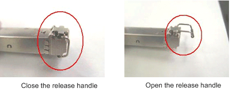
2. Figure 1 shows the releasehandle on an optical module when it is open and closed. When inserting the optical module, make sure that the release handle is closed. At this time, the latch boss locks the optical module. After the optical module is inserted, trypulling it out to see if it is installed in position. If the optical modulecannot be pulled out, it is secured.
Figure 1 State of the release handle
Measures to Prevent Receptacle Contamination
1. Cleaning tissues must be prepared on site. Youneed to clean the optical connector before inserting it in the receptacle. Thisprotects the receptacle against contamination on the surface of the opticalconnector.
Figure 2 Cleaning opticalfibers with special cleaning tissues
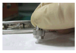
NOTE:
Placeat least three cleaning tissues on the work bench. As shown in Figure 2, wipethe end of an optical connector from left to right or from right to left on acleaning tissue, and then move the connector end to the unused part of the cleaning tissue to continue.
2. Cover an unused optical module with aprotective cap to prevent dust, as shown in Figure 3.
Figure 3 Installing aprotective cap
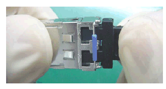
If no protective cap is available, use fibersto protect the optical module, as shown in Figure 4.
Figure 4 Using fibers toprotect an optical module
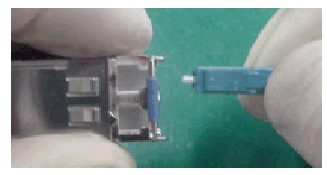
3. Cover unused optical connectors with protective caps, as shown in Figure 5, and then lay outfibers on the fiber rack or coil them in a fiber management tray to prevent fibers from being squeezed.
Figure 5 Installing aprotective cap on a fiber
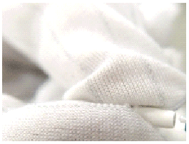
4. If a receptacle or an optical connector hasnot been used for a long time and is not covered with a protective cap, youneed to clean it before using it. Clean a receptacle with a cotton swab, asshown in Figure6. Clean an optical connector with cleaning tissues.
Figure 6 Cleaning a receptacle with a cotton swab
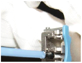

When cleaning a receptacle, insert the cotton swab and turn it slowly in the receptacle. Do not use too much strength because the receptacle may be damaged.
5. If optical signals are lost during theoperation of a device, use the preceding method to clean the receptacle or theoptical connector. In this manner, the possibility of contamination can be excluded.
Measures to Prevent an Optical Modulefrom Being Burnt
1. Before using an optical time-domain reflectometer (OTDR) to test the connectivity or the attenuation of opticalsignals, disconnect the optical fibers from the optical module. Otherwise, the optical module will be burnt.
2. When performing a self-loop test, use anoptical attenuator. Do not loosen the optical connector instead of the opticalattenuator.
Precautions
1. The optical connector should be vertically inserted in the receptacle to avoid damages to the receptacle.
2. Fibers must be inserted into optical modulesof the corresponding type. That is, multimode fibers must be inserted into multimode optical modules, and single mode fibers must be inserted into single mode optical modules. If a fiber is inserted into an optical module of adifferent mode, faults may occur. For example, optical signals will be lost.


